RGH3 Modding an XBox 360
2024-01-11 23:24 - Gaming
I have a significant collection of video game consoles. Wherever possible and practical, I prefer to "mod" them. Mod is short for modify, and generally means lifting the restrictions that they come with — mostly for copy protection. These mods have many benefits but a significant one is being able to run games without relying on the optical drive the whole time. In these ten or twenty year old devices, the moving optical drives often fail.
Back in 2015 I tried to mod the XBox 360 I had at the time. Long story short, I failed to remove the "x-clamp" (which holds the heat sink down to the APU) and damaged the logic board in the process. (I still have all those parts, maybe I should try some trace repair again.) More recently I accepted an XBox (OG) and XBox 360 that was being given away. Then even more recently I heard about the "RGH3" mod. The 360 has pretty good protection built in. For a long time, besides some simple piracy-only based modifications "RGH" (reset glitch hack) was the only way to mod a 360 for full control. The idea is based around sending a very brief reset signal to the CPU at just the right time, so that as it is performing verification checks very early in the booting process, the check (and only the check) can be corrupted. Then the console otherwise boots as normal, but has not verified its firmware. This used to take a special extra "mod chip" and quite a bit of very careful wiring. The third version, RGH3, amazingly uses the console itself to send this reset glitch signal. That makes it a comparatively very simple modification: just two wires. (Two permanently, a few more temporarily.)
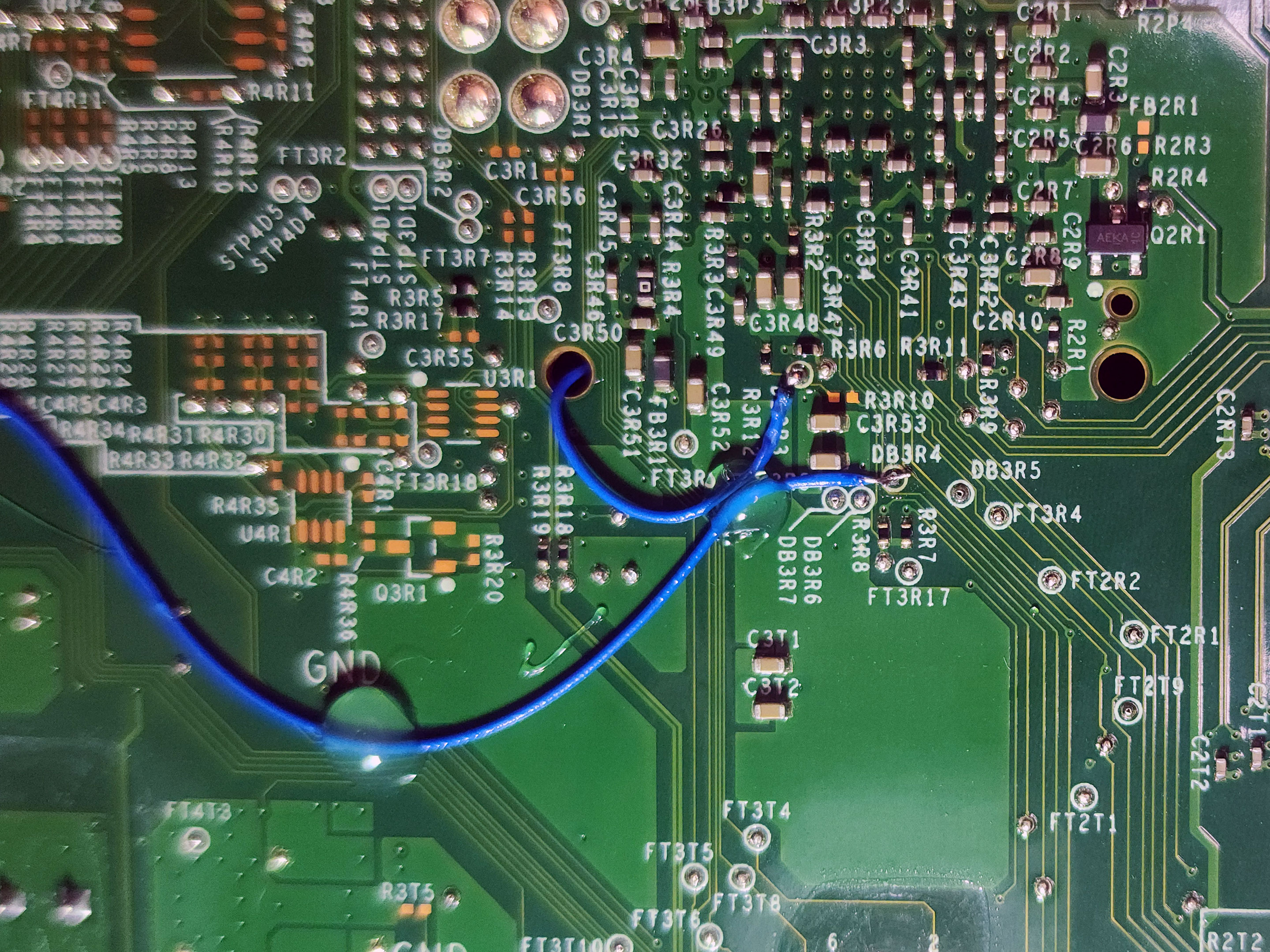
Last month, I opened up the 360. I confirmed that it's a newish (relatively speaking) "Corona" variant. Because it's new, it's designed to prevent RGH style attacks. Because the modding community(/related business(es)) is clever (and a bit lucky) there is a "POST fix adapter" to restore access to the otherwise removed signal trace. It just so happens that this is one of the outermost "pins" of the APU, so a carefully positioned piece of wire can touch it. And the adapter is designed to hold a little pin in just the right spot. That's one end of one of the two wires needed. The picture above is the other end of the two wires. With POST dealt with, these are the two "easy" remaining connections. They're tiny, but they're exposed and directly available. (It's not unusual for all sorts of important signal traces to have test points in commercial products, intended for use during design and manufacture.) I'd estimate that the white circles drawn around these two points, where my added blue wires terminate, to be about one millimeter across. Possibly one and a half. Those blue wires are 30 gauge "wire wrapping" wires. The wire itself is 0.255 millimeter in diameter. The higher of those two solder points I did rather well on. The lower/rightmost one isn't as great. The exposed wire is too long and the solder has barely attached it. But attached it is! I got away with it.
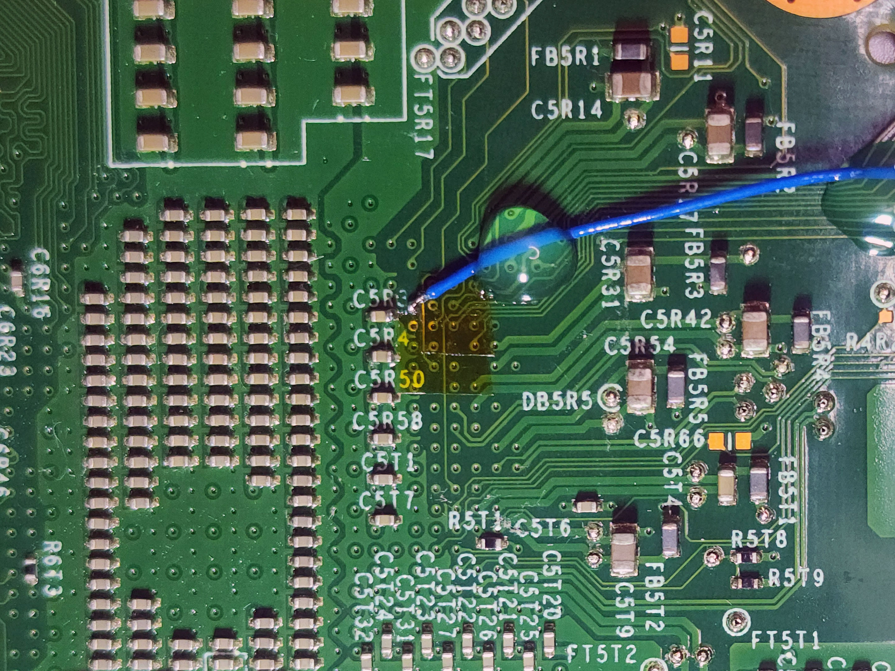
Here's the remaining wire end. It's attached to a via, which starts off covered in solder mask. The point of this mask is to prevent solder from going here. This must be scraped off, without damaging the tiny and fragile exposed copper part of the via. I did so with a fiberglass "scratch pen". I slightly exposed an adjacent via and track, so those were covered with some polyimide tape before proceeding. For this one, the via-as-solder-point is hardly wider than that quarter-millimeter wire. This one took a few tries, and I ended up leaving a little extra solder on the capacitor. Once this tiny joint was complete however, I didn't want to mess with it.
I added some tiny dabs of hot glue to keep the wires in place, to avoid breaking these fragile joints through mechanical fatigue. I also added an in-line resistor on one of the lines as suggested by the guide I was following. The following steps were mostly software based. When first flashing Xell (xenon linux loader — xenon is the code name for the first XBox 360 variant) the first time it didn't take. I turned the 360 on and Xell should have launched, but the standard retail dashboard did, instead. After sleeping on it I wrote Xell a second time and somehow this time it worked. This is just the first step however, unlocking the next step: the XeBuild which actually modifies the console's behavior. (It requires knowing the per-device encryption key, which Xell somehow is able to read.) This also did not boot after flashing it, this time Xell remained. I tried writing a second time, and this did not work. But Xell also supports writing this sort of update, so I tried a third time using it (instead of the PicoFlasher I used to get this far) and it worked. From there I just had to install some custom software and I was in full control, huzzah!